Transfer stations are a deceptively simple concept. Once you get past the high-level concept of an enclosure for tipping material from smaller vehicles and loading those materials onto larger ones for transport, questions begin to present themselves regarding how to best perform that task, how the site will function and how it will accommodate future changes.
Through the course of our work, we have observed and studied hundreds of transfer stations across the country. Many are great facilities run by skilled operators, while others need to be reevaluated regarding layout and operations procedures. One constant we observed across the board is that there are typical mistakes that seem present in many transfer stations. These mistakes can be grouped into the following categories: planning and programming, site design, facility design, construction, operations and future accommodations.
Initial planning and programming
The planning and programming stage of a transfer station project is critical. It is here that the base design requirements are determined and the entire direction of the project is set.
To incorrectly gauge facility material throughput needs, or to inadequately plan out waste ban material and nonmunicipal solid waste (MSW) material storage, is a common error at this stage. Many teams at the planning stage focus on the primary material to be received and size the building material pile storage based on that. Most operations have a need to divert some materials from the primary stream, including green waste, white goods, batteries, mattresses, construction and demolition (C&D) waste, single stream-recyclables and household hazardous waste (HHW). While these items may represent a fraction of your daily volume, they often need a location to be stored until sufficient materials are present to be loaded out. Depending on the variety and volume of materials, this can take up a significant floor area, which would otherwise be available square footage you may not have initially had.
Another common error is incorrectly determining the incoming material sources and how that impacts the building design, tipping, queuing and scaling. It is common to see sites designed around the ability to load material into transfer trailers at a determined rate to confirm building design throughput. However, a determined effort at the initial planning stage should be to plan the types of vehicles necessary, including residential and commercial collection vehicles, roll-offs, local residents and tractors and trailers. An effort should then be made to assign cycle times for these vehicles to scale in and out and determine how long it takes them to tip at the building. If possible, the times of day this material will be arriving at the facility should be considered to help confirm the queuing at the scales. This review should include an analysis of how much volume is internal versus third party as that may help determine whether radio frequency identification (RFID) readers would be necessary. This planning effort will determine the number of scales and tipping doors needed to accommodate the incoming material stream throughout the day as each vehicle type will require different amounts of time to offload their material.
As you work to determine the facility requirements to handle the incoming and outgoing materials, you should work with the operations team to determine how they want the facility to be run.
Neglecting to determine if the facility operator will be live loading outbound material or using a drop-and-haul approach to load and stage outbound trailers is another common error. Live loading is where the transfer trucks arrive at the site and proceed to the loading position to have the empty trailer loaded with material prior to leaving the site. Drop and haul involves a truck and an empty trailer arriving at the site, where the driver drops off the empty trailer and picks up an already-loaded trailer. Both approaches have their advantages and drawbacks, but if the site is going to operate as a drop-and-haul, there needs to be trailer parking and circulation areas defined. A live-load approach may require more queuing areas for tractors and trailers because they tend to arrive in groups of two or three.
Site design
Civil engineers have a challenging task in designing transfer station sites to address the circulation of vehicles, as well as conveying stormwater on the property and addressing a variety of programming needs.
A common mistake we see is inadequate pavement in areas of accelerated loading at transfer station facilities. We tend to see these issues arise in asphaltic pavements at tipping aprons, as well as at hard turns on the site. Another area of typical pavement failure is at each end of the truck scale. As a best practice, there should be 20 to 30 feet of concrete after the end of the ramps. Ideally, all site pavements will be heavy-duty concrete, but the budget often does not allow that. As a compromise, we try to have the tipping aprons in concrete as well as tight turns where possible. If the site will be a drop-and-haul type load-out, a strip of concrete should be provided for the trailer landing gear.
When a civil engineer works to develop the site plans, another consideration should be made toward addressing wind-blown debris. Most areas have prevailing wind directions and those should be taken into consideration with how the building is oriented, ideally with the tipping doors away from the wind. Another consideration is that if there is a truck load-out tunnel, it should be designed with doors to help minimize the wind-tunnel effect.
Regarding vehicle maneuvering on site, there is a difference between what is technically possible and what is reasonable and safe. We often see sites designed where the vehicle backing maneuvers are on the passenger side of the residential or commercial collection vehicle, which results in a blind maneuver. In addition, many transfer station site designs have aprons at a steep pitch and long distances to back up to the tip. Many transfer stations also have several points of crossing traffic, which represents a safety risk. The civil engineer should work to avoid or minimize these risks by paying attention to which side of the vehicle the backing maneuvers are on, eliminating crossing traffic and keeping traffic circulating counter-clockwise as best practices for transfer station traffic routing design.
Facility design
As the project progresses to the actual design of the transfer station building, there are several mistakes we see that can be avoided.
When the structural engineer is designing the tipping floor slab, they must plan for wear in the design of the concrete as well as in the placement and specifications of the reinforcement slab. We often see facilities with severely damaged floors due to an inadequate floor design.
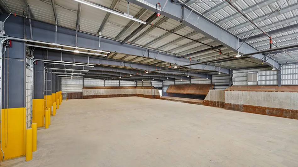
Most new transfer stations are required to be enclosed buildings, which include overhead doors. These doors are a critical and expensive building element that requires proper care in the design of the facility. Many transfer station facilities do not provide adequate protection for the door jambs and put the overhead door tracks at risk. When designing around the door jambs, provide robust concrete-filled steel bollards. Place the bollards so they overlap the door jamb, otherwise the door jambs are at risk.
Door height is another common mistake. While all vehicles should be able to fit through a 14-foot-tall door, when collection vehicles or roll-off trucks are tipping, doors closer to 30 feet may be needed. The design team should consult with the operations team to ensure the specified doors are both wide and tall enough for safe and effective operations.
This cannot always be avoided, but where possible, the building should be designed to avoid building roof downspouts discharging water onto the tipping apron. This can be achieved by placing tipping doors on one wall and designing the building with a single slope roof conveying rainwater away from the apron, or by providing subgrade pipes to convey downspout run-off. Regardless, this approach is preferred as it avoids ice accumulating on the apron in northern climates. In all climates, less stormwater on aprons is a best practice to minimize total suspended solids (TSS) and trash in stormwater inlets.
When the structural engineer designs the foundation system, they should avoid both hairpins and tie-beams in wearing slabs. As the wearing slab may require replacement of sections throughout its service life, using any of that slab as a part of the foundation system is risky, especially if the team replacing the floor in the future is not aware the floor slab is carrying lateral loads of the metal building.
Construction
Without proper guidance and experience, construction teams often make the same mistakes at transfer stations.
Often, for the tipping slab, the construction teams are proud of the hard-troweled mirror finish they can put on the concrete. This can become a serious operational challenge once the operations start and the wheel loaders are unable to get any grip on that slippery slab, especially when wet materials are being tipped. To address this, we recommend a screeded and troweled finish but avoid hard troweling to afford some grip on the yellow iron.
The proper slope of the tipping slab in a transfer station is another challenge for construction teams. Leachate management is a critical design and operational challenge for all transfer stations. The tipping slab should be designed to convey leachate away from tipping doors, and the construction team needs to ensure that the pitch is maintained. It is not unusual to see the concrete pitch at the tipping doors be nominally flat or even pitched slightly toward the exterior. Work with the construction team so they understand the importance of properly pitching that concrete, as it is a very difficult and expensive repair once poured.
It is not uncommon for the building plans to be designed for a specific scale and layout of its foundations. Often, when it’s time for submittals and final scale selection, the original foundation design is superseded by an updated one. If another vendor is selected, it may similarly need to change. Many times, this information does not make its way back to the structural engineer and the foundation plans are not updated. The scale foundation plans are then built per the structural set, and when the scale arrives for installation, it does not fit. Ideally, the scale will be ordered during the design phase to lock in that design, but the general contractor needs to ensure what is bought out goes through the structural engineer during the submittal process.
The practice of routing electric conduits beneath the floor slab is a typical construction practice that should always be avoided when building a transfer station. Without direction otherwise, the electrician will often lay the conduits on top of the subgrade. The conduits are encased in the floor slab pour, which will often be severed by full-depth replacement. Additionally, the liquids present on the floor of a transfer station are corrosive and may impact the conduits. Ideally, the electrical conduits should be routed overhead. If they must be routed under the slab, they should be buried in the subgrade.
Future accommodations
No one has a crystal ball to know how a site and its operations will change over time. However, we see typical mistakes many transfer station designs make which complicate future needs.
A very common mistake we see is that the building and site make no plan or accommodation for future building growth. Site plans allowing no space on either side of the building prevent the addition of future bays. The building design should include a design for the metal structure with a bearing end frame, which would allow future expansion with minimal structural rework. These approaches are typically inexpensive up-front but represent significant savings in both cost and disruption to future operations if future expansions are needed.
Another common error is in the routing of underground utilities. If the building has anticipated areas for expansion, the subgrade utilities should be located out of those areas.
There is no such thing as a perfect design, a perfect building or a perfect operation. We are all trying to do the best we can with the information we have. It is important to occasionally step back and look at what is working and what may need further refinement. By identifying typical errors and oversights we see at transfer stations, we hope you can avoid them at your transfer station.
Evan Williams is a design project manager at Cambridge Cos. Inc., a design-build firm specializing in the environmental, waste and trucking industries for more than 30 years. During this time, Cambridge has completed more than 200 solid waste design-build projects for transfer stations, recycling centers, material recovery facilities (MRFs), renewable natural gas (RNG) facilities, hauling companies, maintenance facilities, landfill support facilities, office buildings and more. The Cambridge team continually monitors industry trends and the ever-evolving needs to provide relevant solutions when planning and building new facilities to ultimately benefit clients with industry leading design-build solutions. For more information, visit Cambridge's website. You can also contact the author via email at Evan@cambridgecoinc.com.
Latest from Waste Today
- Goodwill recycles textiles as part of pilot project
- Bridgestone introduces retreating plant virtual tour
- New York landfill owners accused of permit violations
- Analysis: Chemical recycling’s ‘inflection point’ nearing
- Machinex system in Québec targets organics diversion
- New Hampshire Senate defeats bills to block new landfills
- WM updates Pittsburgh Recycling Facility
- LRS adds robot on its last-chance line to target UBCs


